


The Dependency Graph maps every node and its dependencies in an automation as a directed graph, letting you see execution order, identify steps that can run in parallel, and assess the impact of a failing node at a glance.
Overview
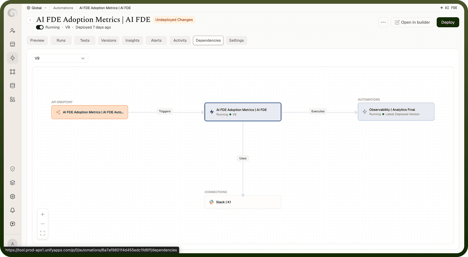
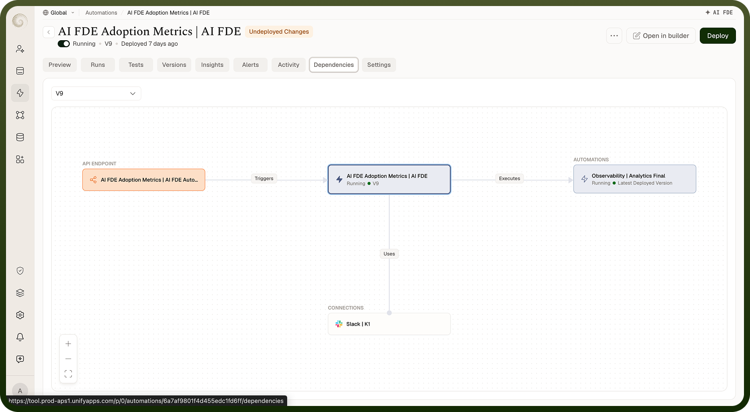
The Dependency Graph is a visual representation of the tasks and their dependencies in an automation, showing which steps depend on which and which can run in parallel.
As automations grow in complexity — especially those with loops, branches, and callable sub-automations — understanding the order of execution and the relationships between steps becomes non-obvious. The Dependency Graph maps every node and every dependency between nodes into a directed graph, making the execution structure visible at a glance.
Components
The graph has two elements:
Nodes — each node in the graph represents a task or step in the automation. The node's label matches the display name in the builder.
Edges — directed arrows between nodes represent dependencies. An arrow from A to B means B depends on A: A must complete before B can start. The direction of the arrows encodes the execution order.
Example
In a three-step automation that fetches a Zendesk ticket (A), then concurrently sends a Slack message (B) and creates a Jira issue (C), then sends a summary email (D) after both B and C complete:
A → B and A → C (both B and C depend on A; they can run in parallel)
B → D and C → D (D depends on both B and C; it waits for both to complete)
The graph makes this parallel structure visible without requiring the reader to trace the canvas manually.
Why the Dependency Graph Matters
Correct execution order — Confirms that prerequisites complete before the steps that depend on them, so no step runs against stale or missing data.
Parallel execution — Identifies independent steps that can run simultaneously, allowing the platform to optimize run time by running them in parallel where possible.
Failure handling — Shows which downstream steps will be skipped if a given node fails, making it easy to reason about the blast radius of a failure.
Change impact analysis — Before modifying a node, use the graph to see all the steps that depend on it and could be affected by the change.
Common Use Cases
CI/CD pipelines — Map compile → test → deploy sequences and confirm that each phase has the right dependencies before pushing to production.
Test automation — Visualize setup → test execution → cleanup chains and confirm that teardown steps always run after test steps.
Data pipelines — Trace source ingestion → transformation → analytics dependencies to catch missing or circular dependencies before running a pipeline job.
Notes
The Dependency Graph is most useful when reviewing, auditing, or handing off a complex automation. To use it effectively:
Open the graph before making changes to a node that has many dependents — the graph shows the impact immediately.
Use the graph as onboarding material when a new team member inherits an automation — it communicates the structure faster than a verbal walkthrough.
Look for nodes with no incoming edges (root nodes) and multiple outgoing edges (fan-out points) — these are the critical starting steps where an error has the widest impact.
Cross-reference the graph with the Monitor tab when debugging: if a run fails at a node with many dependents, the graph shows which other nodes also did not execute.
A clear dependency graph is the mark of an automation that was designed intentionally, not assembled incrementally without a plan.